
Porosity in aluminum die casting isn’t just a cosmetic flaw – it’s a structural nightmare. Trapped gas or shrinkage creates bubbles, weakening parts and causing leaks. Actually, industry data shows porosity accounts for 60% of casting rejections in automotive applications. That’s why optimizing your aluminum die casting mould design is critical.
When molten aluminum rushes into the cavity, air gets trapped. Without escape routes, bubbles form inside the casting. Traditional vents are often too small or poorly placed.
Use stepped vents that widen progressively. Place vents strategically at last-fill areas and high points. Interestingly, research by NADCA suggests vent depths should be 0.05-0.15mm for aluminum alloys to balance air escape and metal leakage.
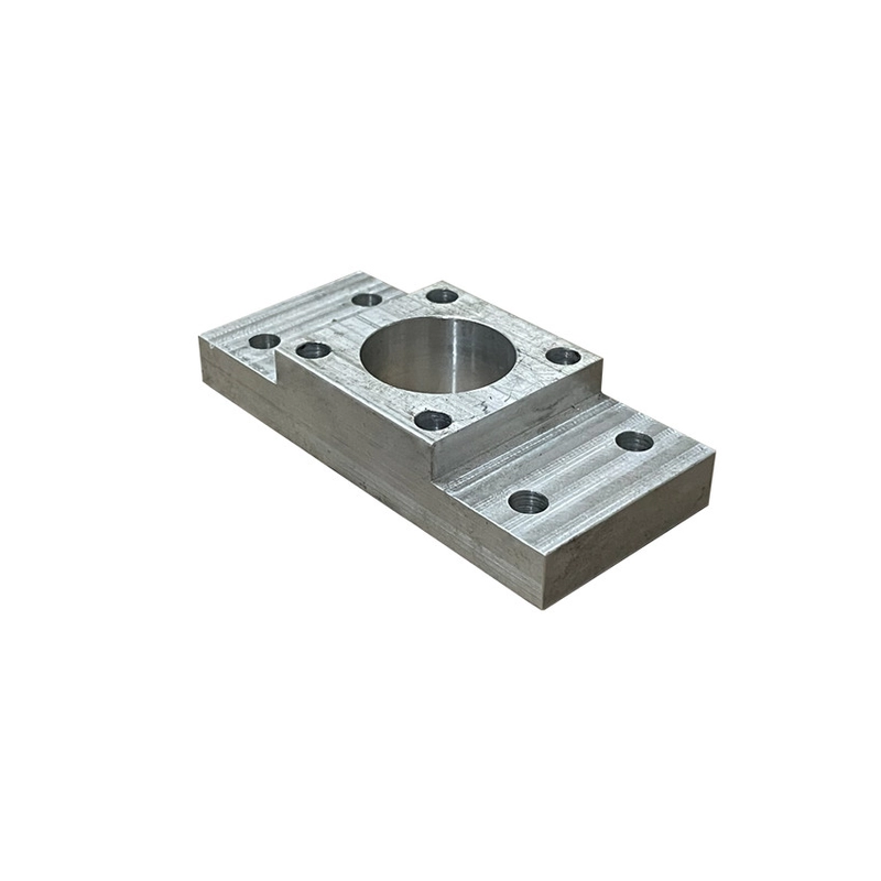
Our team redesigned vents for a pump housing mould in 2025. We added overflow wells connected to stepped vents. Result? Porosity dropped by 40%, saving $18k/month in scrap costs.
Uneven cooling causes shrinkage porosity. The trick? Conformal cooling channels that follow the mould contour. This maintains consistent temperatures, reducing hot spots where porosity forms. For example, complex cores benefit from baffle or bubble inserts to direct coolant flow.
Polished mould surfaces seem ideal, right? Counterintuitively, controlled surface texturing (like EDM finishes) helps gas escape. A study in the Journal of Materials Processing Tech found #320-400 EDM finishes reduced gas porosity by 25% compared to mirror polish.
| Feature | Traditional Design | Optimized Design |
|---|---|---|
| Vent Depth | Uniform (0.1mm) | Stepped (0.08mm → 0.15mm) |
| Overflow Wells | None or Minimal | Strategic Placement |
| Porosity Rate | High (8-12%) | Low (3-5%) |
Over-Polishing Cavities: Mirror finishes trap gas. Use textured finishes strategically.
Ignoring Overflow Wells: They collect cold, contaminated metal before it enters vents.
Inadequate Draft Angles: Increases drag and air entrapment risk. Maintain 1-3° minimum.
Q: How does alloy choice affect porosity?
A: Some alloys like A380 flow better than others. High-silicon alloys generally show less shrinkage porosity.
Q: Can vacuum systems eliminate porosity?
A: Vacuum die casting reduces air entrapment but requires specialized aluminum die casting mould seals and equipment. It’s effective but adds cost.
Q: How often should moulds be inspected for porosity issues?
A: Check critical vents and cooling channels every 10k cycles. Monitor castings for porosity trends weekly.